FSAE Air Flow Bench
Measures airflow characteristics of intake and exhaust components and displays data on a GUI
Problem:
- - No reliable way to measure intake / exhaust performance
- - Team design decisions were based mostly on simulations + analytical estimates (limited real-world validation)
Goals:
- - Design + build a functional flow bench to measure airflow characteristics
- - Implement electrical system and architecture: sensors, wiring, power management
- - Coordinate with mechanical and software team members to integrate system components
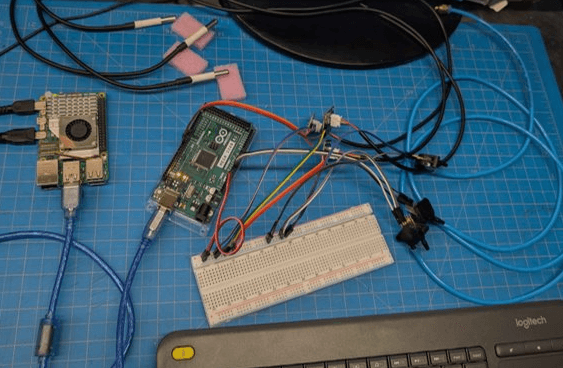
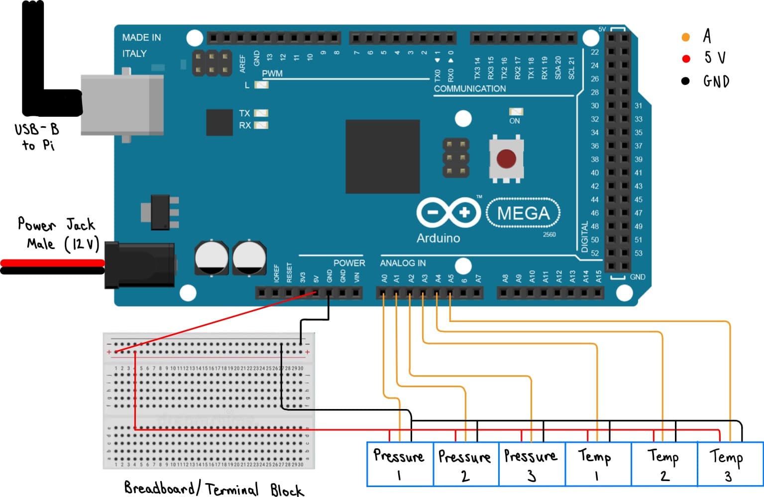
- - Arduino for sensor data acquisition
- - Raspberry Pi runs GUI and calculations
- - 3 analog temperature probes
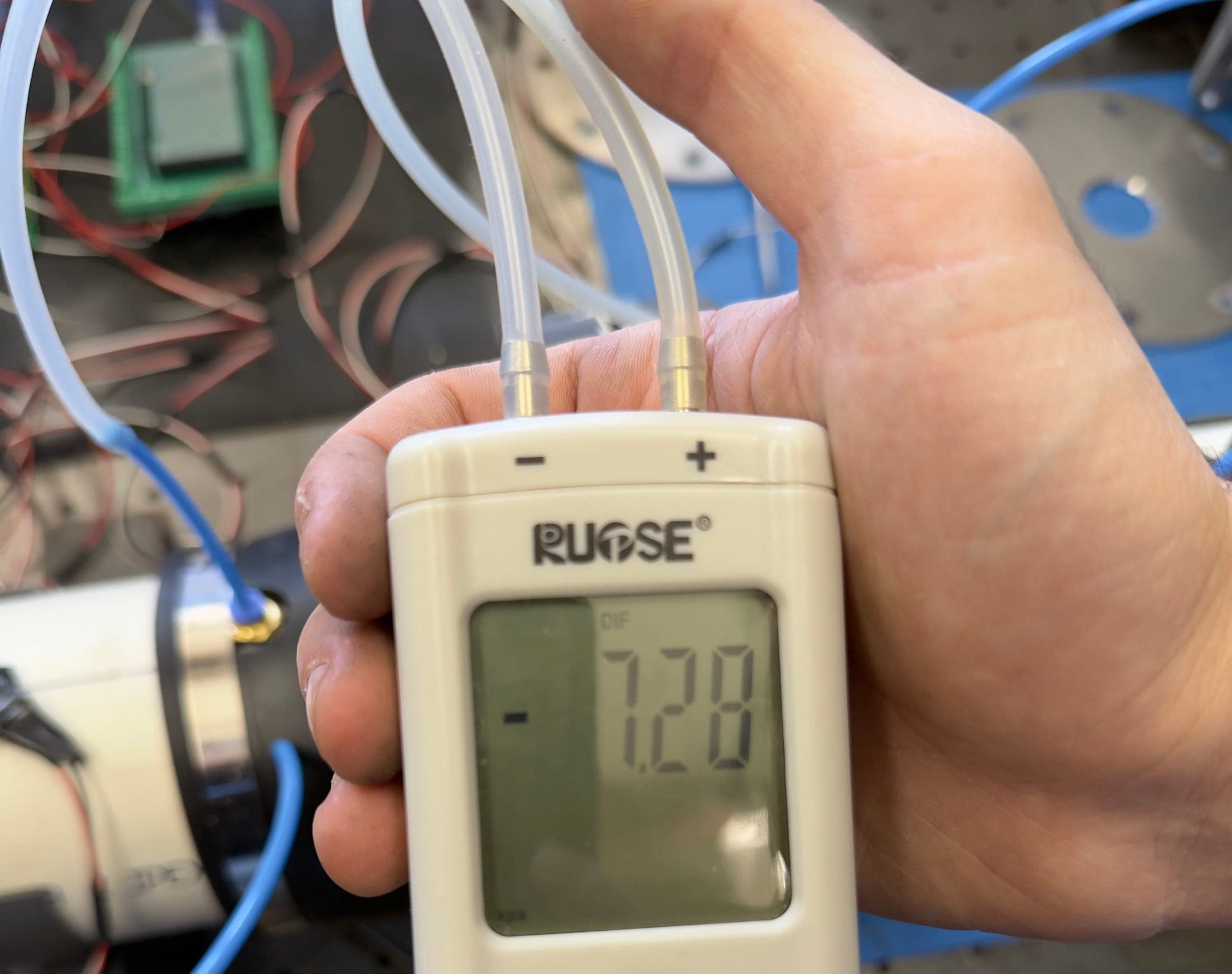
- - 3 analog pressure differential sensors
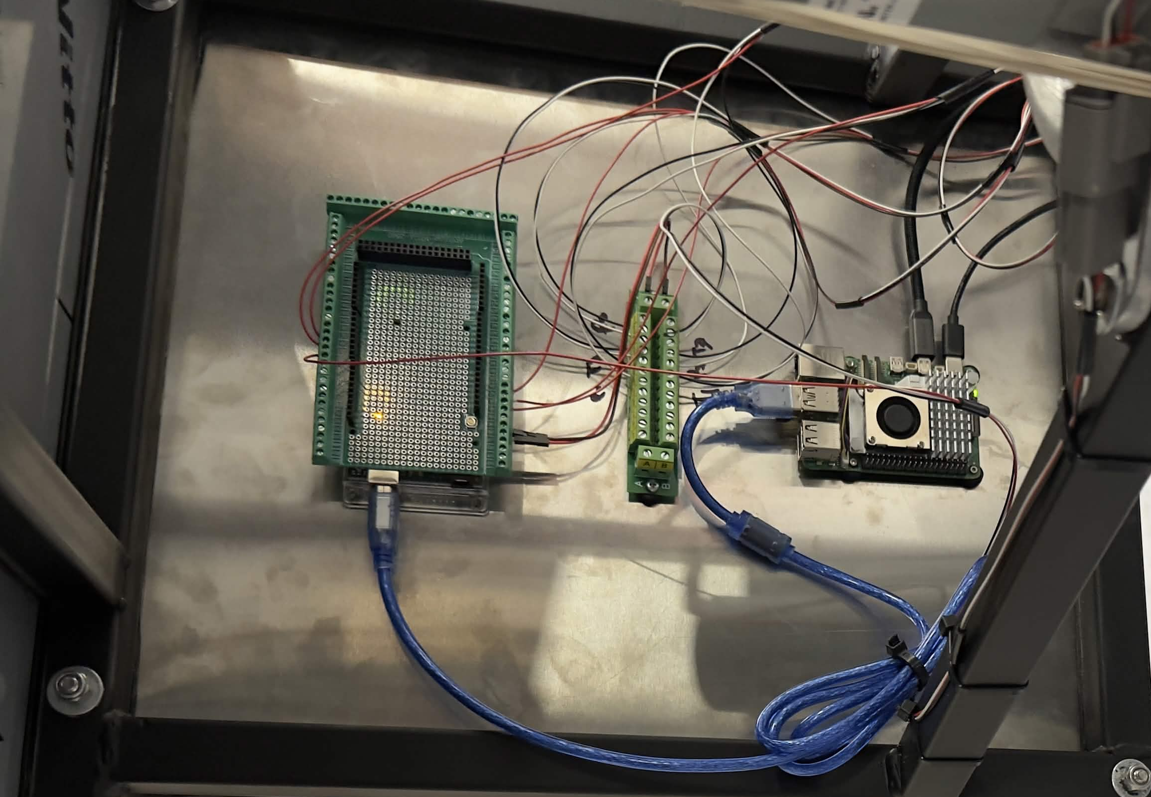
- - Power terminal block with screw in connections for a more sturdy power connection when operating the test bench
- - Three-pin DTM connectors of several lengths for easy disconnect and flexibility for future modifications
- - LOTS of 22 AWG wire to mount the sensors in different areas of the pipe or bench
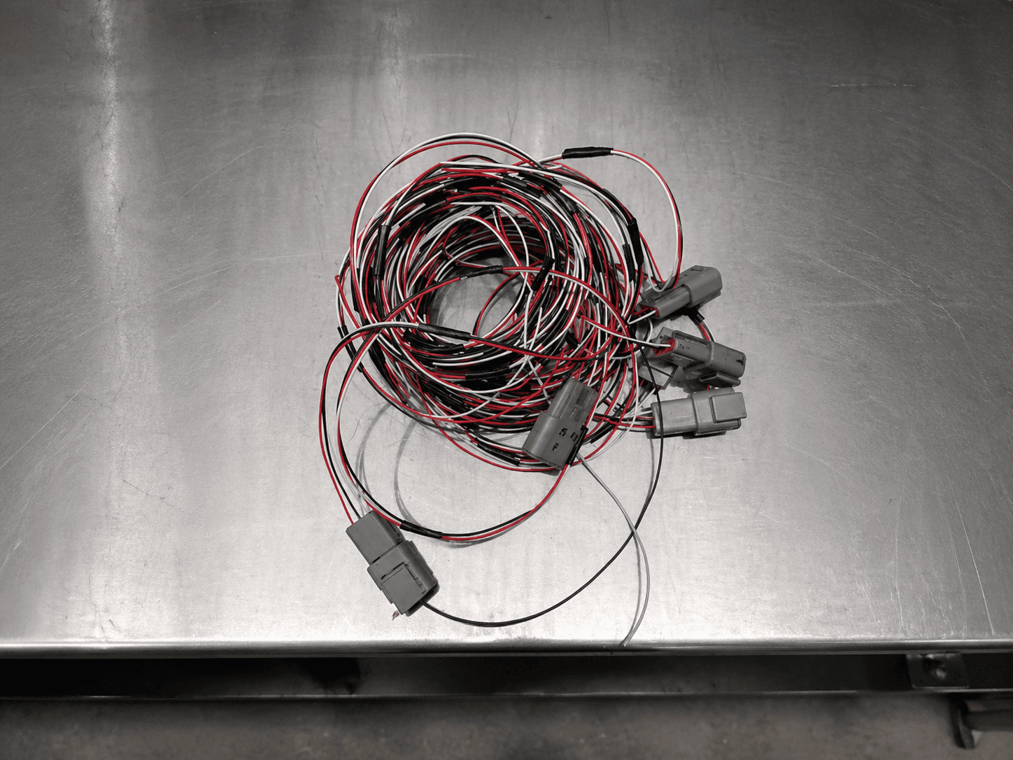
This part of the process mainly involved creating the connectors, crimping, soldering wires, and making sure the wiring was somewhat managed.
Sensors were connected to the Arduino as well as the power terminal block and mounted along the pipe.
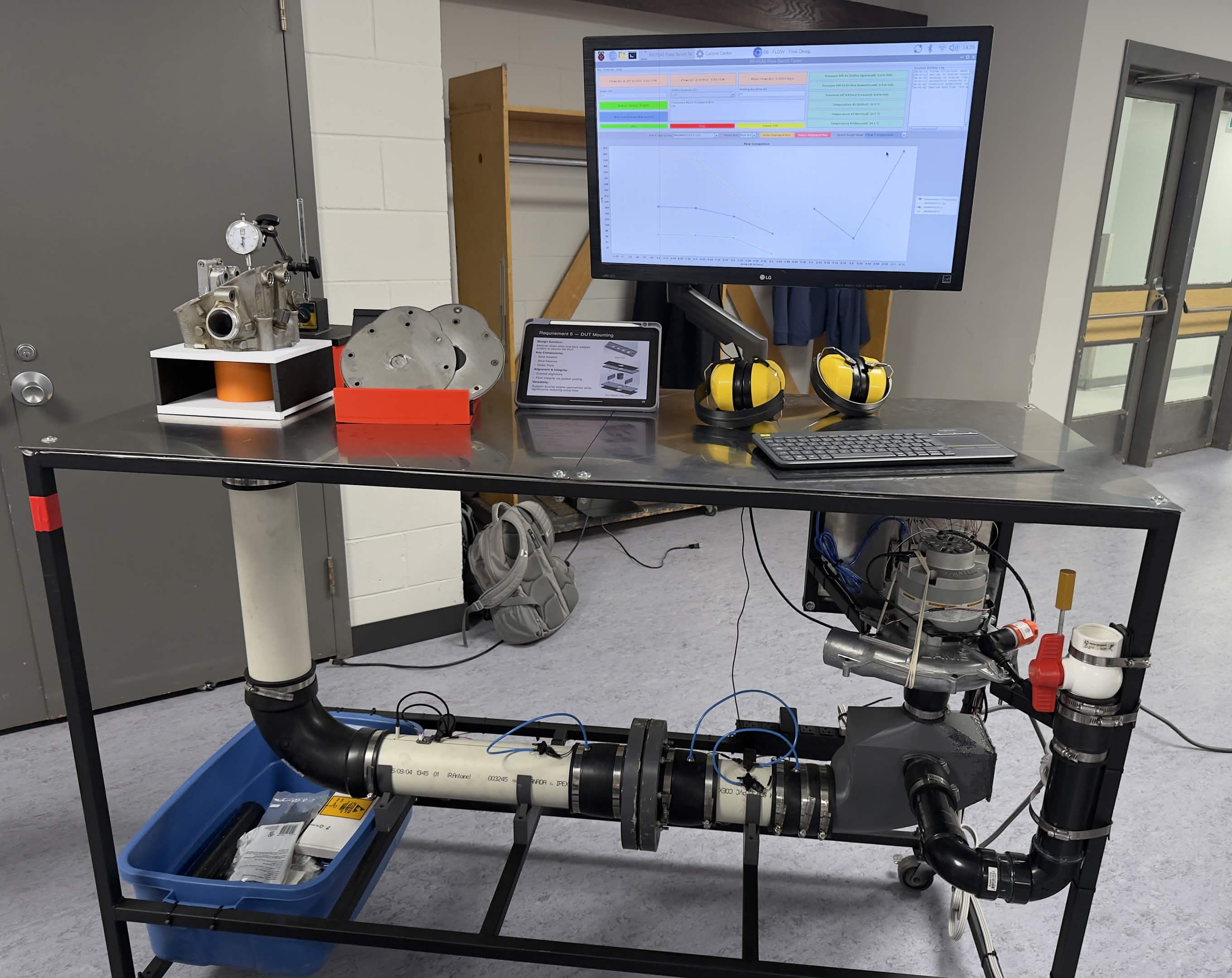
All electronics were mounted together on a panel and put in a designated section under the bench.
A cable extension was required to match the plug configurations of the vacuum motor and a switch was added for additional safety.
Testing:
- - Temporary breadboard connections were used for testing to make it easier to modify and debug
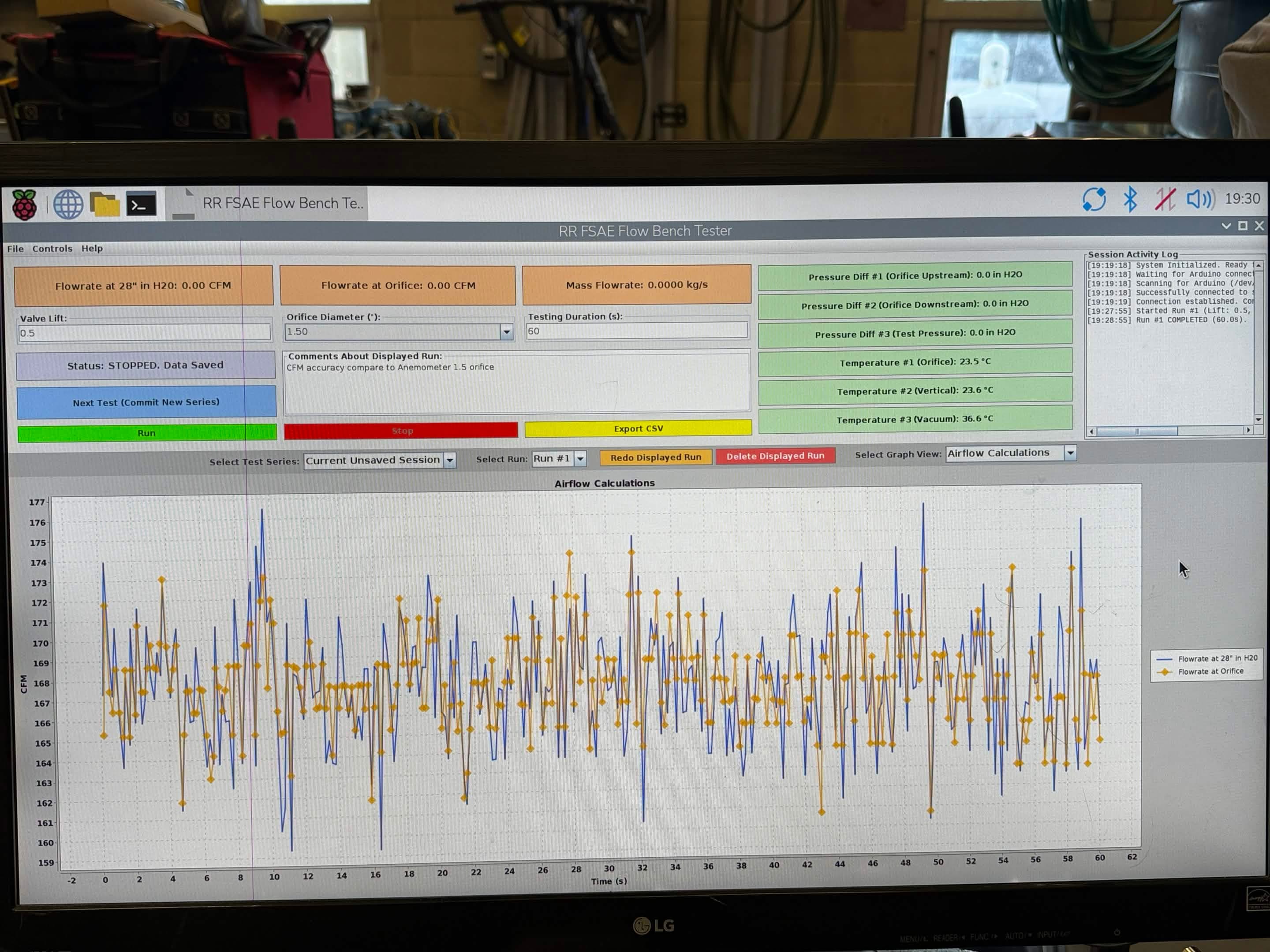
- - Checked to see if GUI would update and display changes in air pressure or temperature from the sensors
- - Compared calculated values to measured values to verify sensor's accuracy
Very positive process overall, with the final design fitting within the original constraints we had set. For a first prototype it was really successful and a system that will also be used and improved upon through many years by our FSAE team.